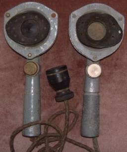
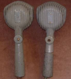
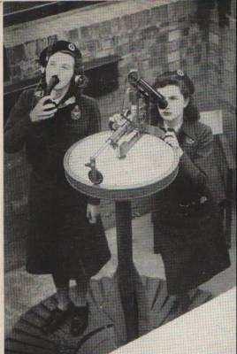
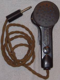
Tannoy hand sets dated 1943 the one left is the handset from a 'Telephone, Loudspeaking, No 2'.
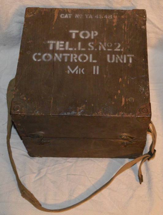
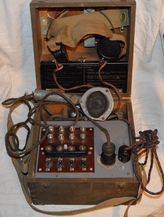
This consisted of an amplifier (control unit) and four speakers that was used by Royal Artillery
troop command posts to transmit fire orders to the guns (one speaker at each gun).
The official name of it is "Microphone, Hand, Power, No 1B' and it's catalogue number is 'YA2814'.
The one on the right, is a YA2813 which is a 'Microphone, Hand, Power, No 1A' and is listed for two
uses: 'Telephone, Loudspeaking No 3' and 'Emergency Tank Crew Control'. Thanks to Rob on the
Militaria collectors network for this information.
|
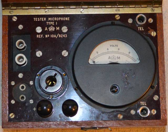
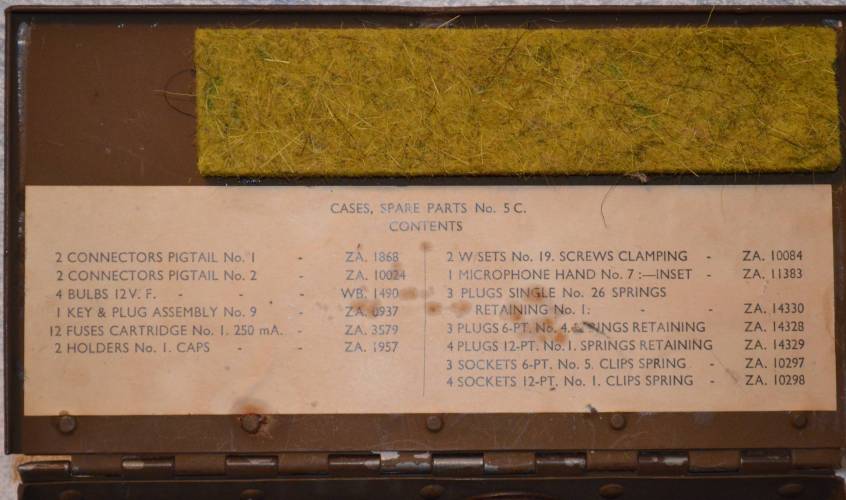
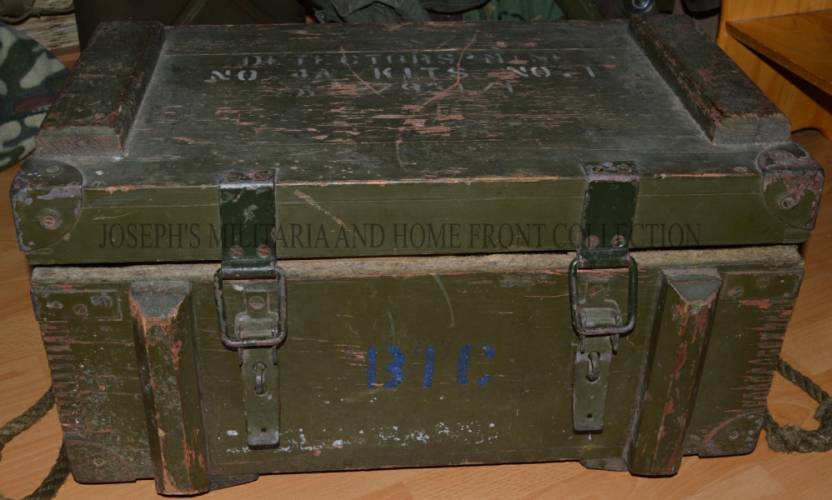
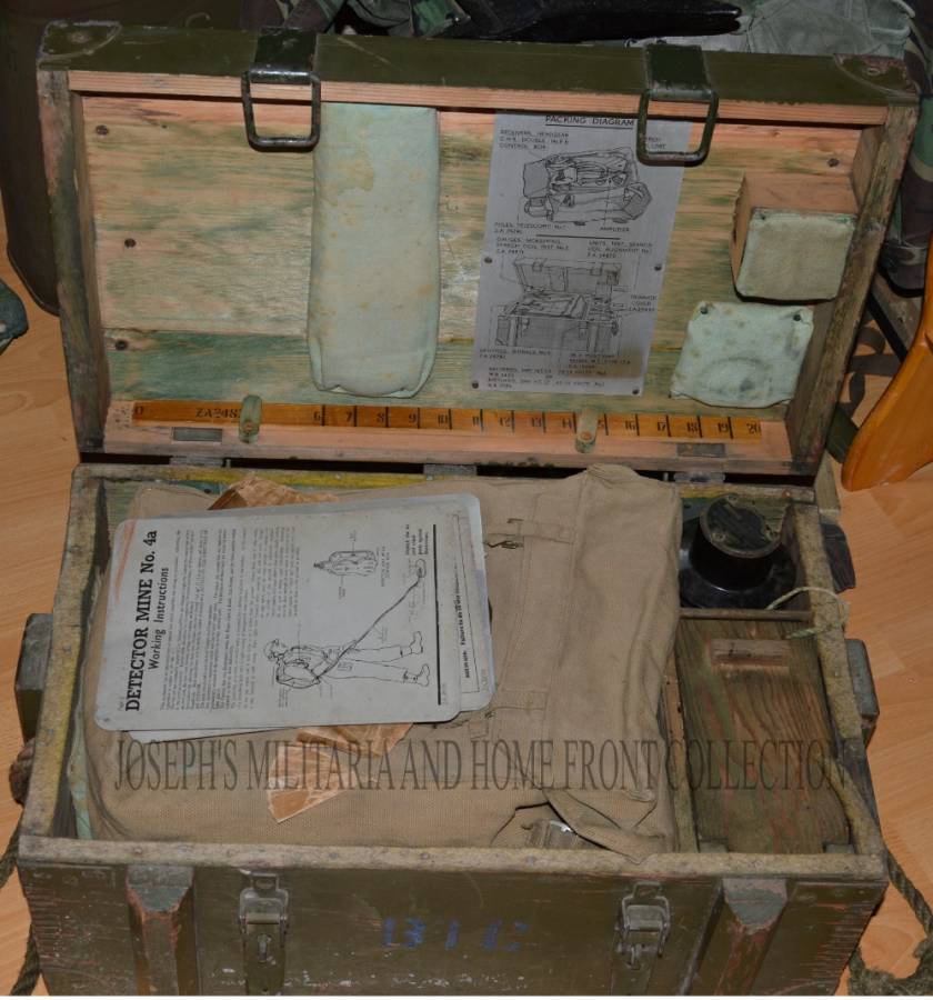
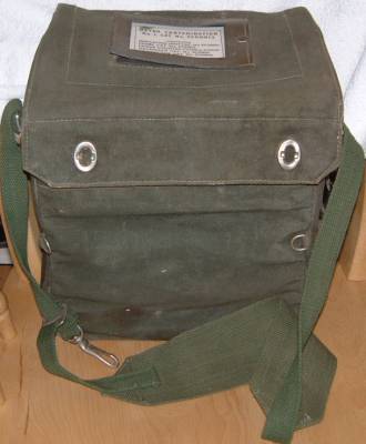
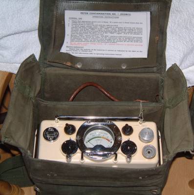
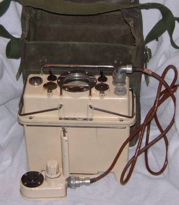
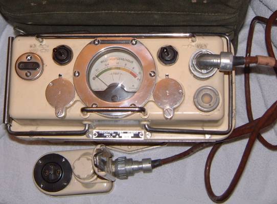
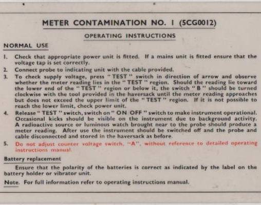
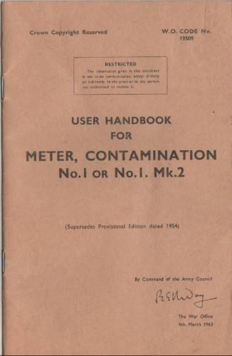
User handbook for Meter contamination No.1 or No.1. MK.2.
| Click here to see all of the the Meter contamination handbook. |
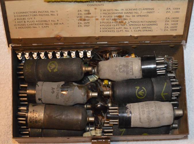
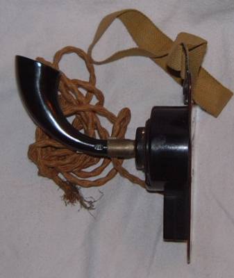
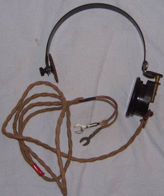
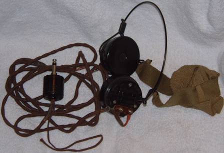
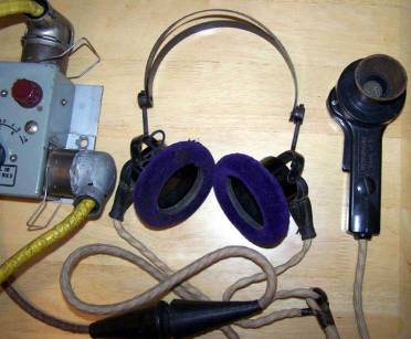
Microphone hand No 3 and and headset
which go with the Wireless Remote Control Unit E (for Wireless set No 19).
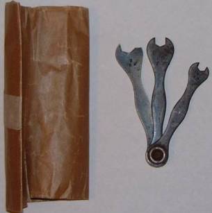
Also a small spanner set which came with them? |
Thanks to Rob on the military collectors network
for all the following information and pictures of his
Wireless Remote Control Unit E and the set No 19 which explaines how it all works and goes together.
|
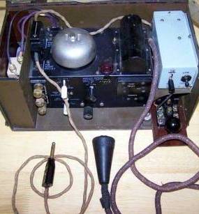
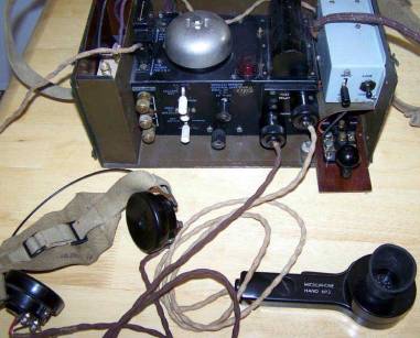
Wireless Remote Control Unit E
|
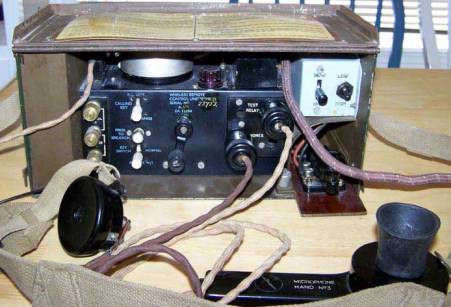
The WRCUE is shown unpacked in the first picture.
It has two connectors, one for the morse key socket on the set, and one with a snatch plug to attach to a Control Unit box instead of the headset.
It has full facilities of a telephone, with bell and dynamo handle for calling.
The front has, from left to right, terminals for telephone wires, control switches (will come to those later),
the ringer handle and sockets for the Microphone Hand No 3, two headphones and a relay test socket. Above the morse key is a box which controls
send-receive switching for the WS19, and a high/low modulation control switch.
|
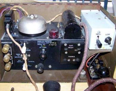
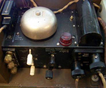
The top of the unit has a plug (this is always used in the position shown,
the WRCUE is a modification of the WRCUB, where this plug was used to switch between use with Wireless Sets No 2, 3 and 9),
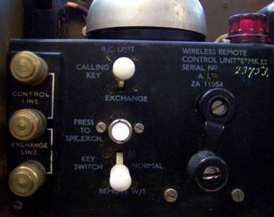
the telephone bell, a relay test light and a covered relay). The central picture shows a close up of the controls on the left side.
The three terminals are for connecting to telephone lines, the middle one being common. The Control Line connects to another WRCUE,
allowing the set to be controlled from up to a mile away. The Exchange Line connects to a telephone exchange (or a telephone such as your Tele Set D or F),
allowing the WS19 to form part of a field telephone system. When being used on the telephone exchange,
the WS19 operator has to listen in on the WRCUE and manually flick the Send-Receive switch on the modulation box.
The three control switches next to the terminals are:
Top: Switches between the Exchange and the distant WRCUE when calling the operator at either using the ringer handle.
Middle: This is a push button used to talk to the Tel Exchange operator while the Distant WRCU operator is using the WS19 morse function (i.e. W/T operation).
Bottom: The switch selects who is connected to the WS19 morse function. At Normal it is the WRCU attached to the set, at Remote W/T it is the distant WRCUE.
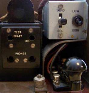
To the right of the ringer handle are the sockets for the phones and mike. The socket marked Test Relay is used to test the function of the relay under the tombstone shaped cover above.
The plug that normally goes to the WS19 morse key socket is plugged in and the morse key is pressed. If all is functioning correctly the red light will come on
|
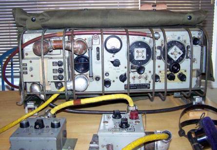
Wireless Set No 19 Basic Setup.
|
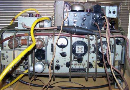
The pictures above show the basic 19 Set layout.
The set itself is actually three sets in one: the A Set (2 - 8 MHz), the B Set (229-241 MHz) and an Intercom system.
Originally the set was designed for use in AFVs, with the B set for tank-to-tank communication and the Intercom for the crew, although it was used in many roles including a ground station.
To allow for flexibility, the radio was controlled via various Control Unit boxes, the actual units used depending on the particular installation. My pictures show the 19 Set mounted on a carrier,
with protective grilles and a waterproof cover, with the power supply on the left of the set.
I haven't included any aerials in this picture or the aerial matching variometer.The brown lead at the top of the set is the A set aerial connector that goes to the variometer.
The B set aerial lead attached to the round connector just left of the meter.
|
 |
 |
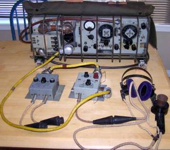
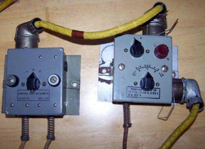
The Control Units are connected to the set by the yellow cords,
which can be any length depending on the particular installation.
The No 2 Unit is the operator s unit and the No 1A provides facilities for two extra users
(in a tank these would often be the commander and gunner). Further boxes could be added on for drivers etc,
but these would only operate on the intercom system. You can see that each box has a switch to enable use of the A set, B set or IC system.
The operator s box can also be used for rebroadcast, that is, signals received on one set can be sent on another (i.e. B to A, A to B), using the N-R switch (Normal-Rebroadcast).
The last picture shows the standard early headset with Microphone Hand No 7, which connects to the Control Units via the cone shaped rubber plugs, referred to as snatch plugs .
|
 |
 |
Finally, some general views of the WS19 and WRCUE set up.
The lid of the WRCUE is hinged and once set up the top can be fastened down as shown,
just leaving the front open. As the WS19 operator has to stay with the set, the WRCUE is placed near the set in use.
A typical setup would be with the remote control on top of the set as shown or in front of it. I have shown the Control Unit
No 2 placed on top of the set, however, in a vehicle this box would be permanently bolted somewhere inside the vehicle.
|
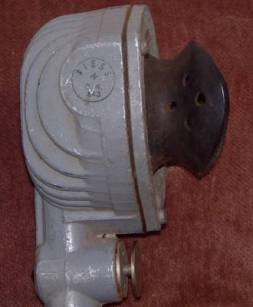
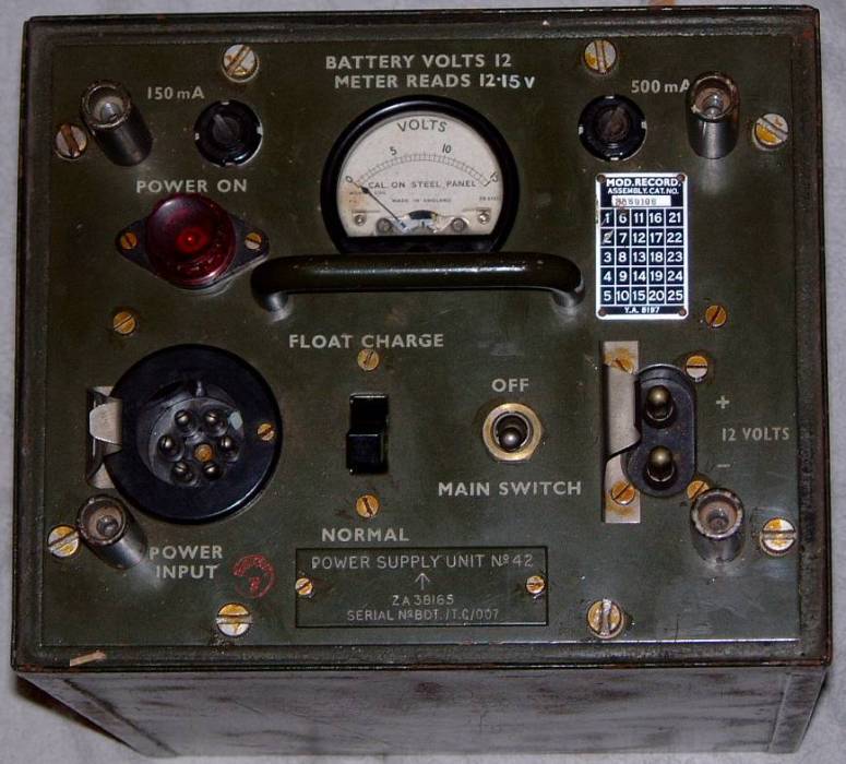
Power supply unit No42.
Power pack for a military vehicle radio. Power supply for the Burndept BE201 radio.
This was a commercial aircraft frequency radio, usually used linked to an Army Wireless Set 62 to
provide relatively mobile air-to-ground communication. Prior to this the Army used the
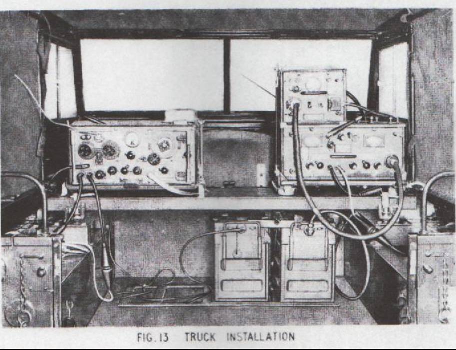
Burndept CN348 radio with the WS62. The next picture shows the position of the power unit when set
up in a truck its at the top right of the picture. Thanks to Rob and Steve on the war traders guild
for this information.
|
 BACK TO MILITARY EQUIPMENT BACK TO MILITARY EQUIPMENT |